Background
Some ideas never seem to go away, this one started in 2013. Sitting in cafe, my mind wandered from the theoretical stuff I was learning during an MSc, and I had the idea to create a large display from seven-segment displays.
Electronics was a hobby, but I had no idea where to begin, and after a bit of research I saw that Skot Coshere had pretty much done exactly what I was thinking. Kudos to him, he did a great job.
A couple of years later, I made a small (12 x 3 digit) attempt at a display. It was a breadboard prototype and the reality was that I just wasn’t capable of making something bigger.
Fast forward about five years (Jan 2020) and for some reason, I found myself looking at some cheap LED drivers on eBay, the drivers that Skot had used in his project. They seemed perfect for the job and I went ahead and bought a load.
After a beer with a friend and then a chat with a curator, my idea was accepted for an exhibition which was 6 weeks away, I had the deadline I needed and an excuse to not just work on client projects! (The exhibition never happened because of Covid-19)
By this time, I had a few projects under my belt and I had learned a few things about electronics. I had used the PRU on the BeagleBone Black to control lots of solenoids, and later a number of LED panels. I love the way the BeagleBone has the comfort of Linux but also the programmability of the PRU and thus interfacing with the real world. With the introduction of the PocketBeagle, it felt like a no-brainer to use it for this project.
The PCB
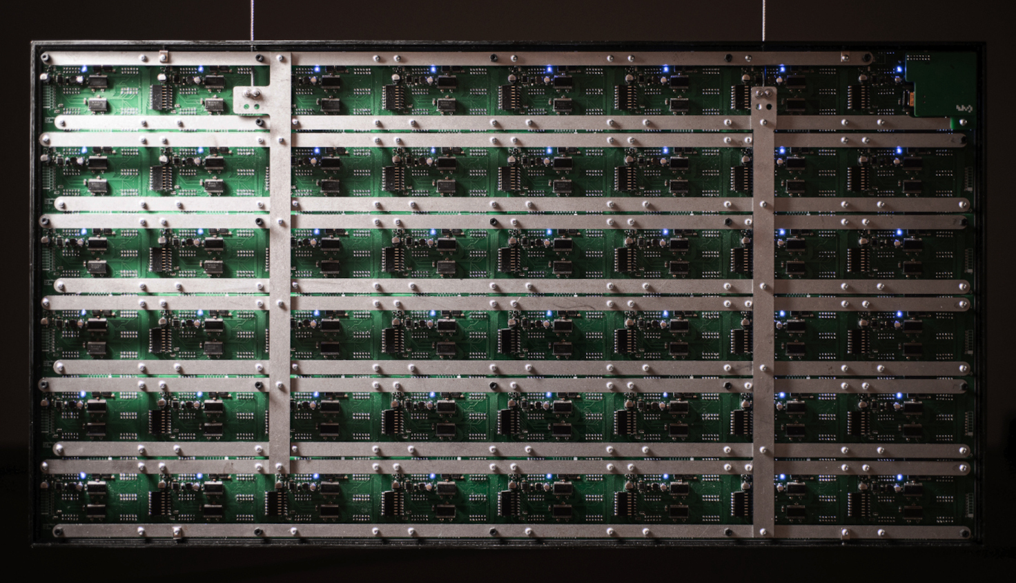
The display is made from 8 x 6 = 48 PCBs, each of which controls 8 x 4 = 32 digits via two TLC5920 LED drivers.
The PCB can tile in two directions, either taking data from the top or the right side and outputting to the bottom and left side. Up to eight channels can be fed in from the top, the first channel gets routed though the LED drivers and then comes out of the left side. All other channels are shifted by one and routed out of the bottom.
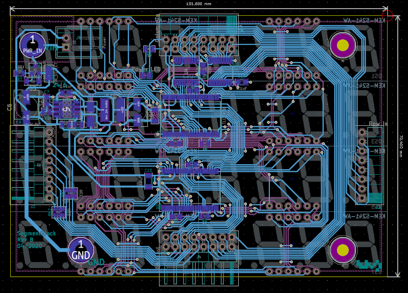
This allowed me to start with a number of parallel streams of synchronous serial data at one PCB (in a corner) and the connections between the boards would channel the data to the right place.
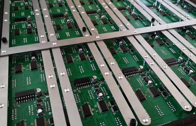
The power to the display comes from a steel lattice that also provides structural support for the PCBs. A 48V supply is connected to two lengths of steel wire that attach to the vertical bars, these then provide power to all the PCBs via the horizontal bars. A thin insulator is between some of the vertical and horizontal bars to prevent shorts.
Pads on the PCB, via standoffs, connect the lattice to the PCB where a buck converter supplies the 5V that the drivers require.
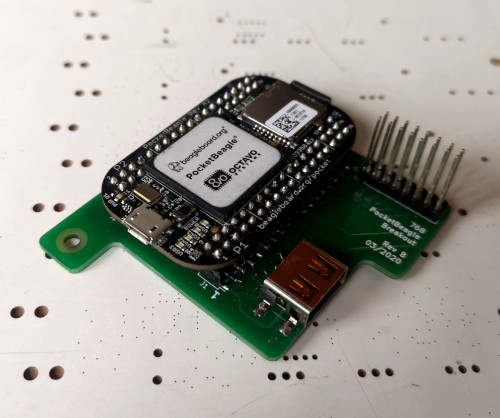
PocketBeagle
The beaglebone runs a program written in C that listens for frames over UDP. No processing is done on the beaglebone, all the pixel manipulation to get the data in the right order is done in the video processing stage. The PRU code is written in assembly and bit bangs the data to the drivers.
I achieve a number of grayscale levels by using binary code modulation. I wanted to get 8 bits of colour depth on the segments, but given the arrangement of the PCBs and the fact that the LEDs are already multiplexed (only an eighth of the LEDs are on at any one time), I couldn’t get this much depth without getting a very noticeable flicker. In the end I had to settle for 5 bits, so 32 levels, but of course in reality it was less because of the non linearity of our perception of LEDs.
Software
I wrote a C++ program (using the great Cinder framework) to read videos and images and work out how the segments should be lit. Within the program, you can load media, move it around and control playback. There are also options for gamma correction, bit depth and how to convert colour to grayscale.
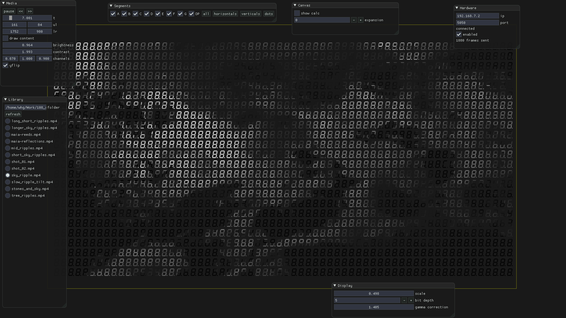
Instead having a LUT for each pixel’s segment, I used the GPU to work out which pixels in the source footage are over a segment, by writing a fragment shader to paint the brightness of the pixel (red channel) and index of a segment (green & blue channels). So the fragment shader outputs something like:
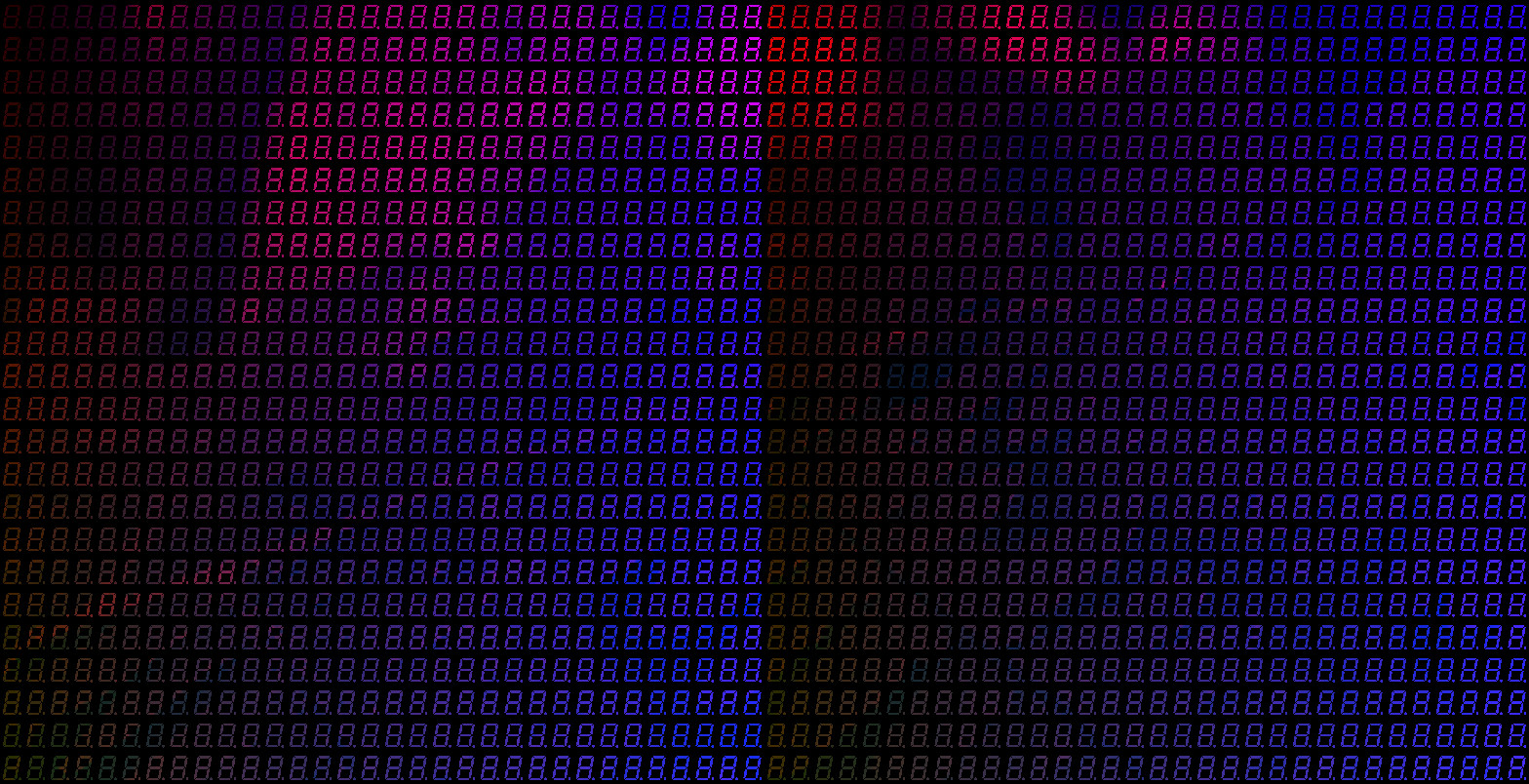
I then read this back from the GPU memory and accumulate all the brightness levels for each segment. There are also a few other GLSL shaders that do things like brightness & contrast and increasing the area of a segment to take account of more pixels.
You can stream frames to the display as well as save them.
Finally, there are a bunch of Python scripts that do things like: drawing text, colour correction for segments, playback of a set of saved frames and more.
Assembly
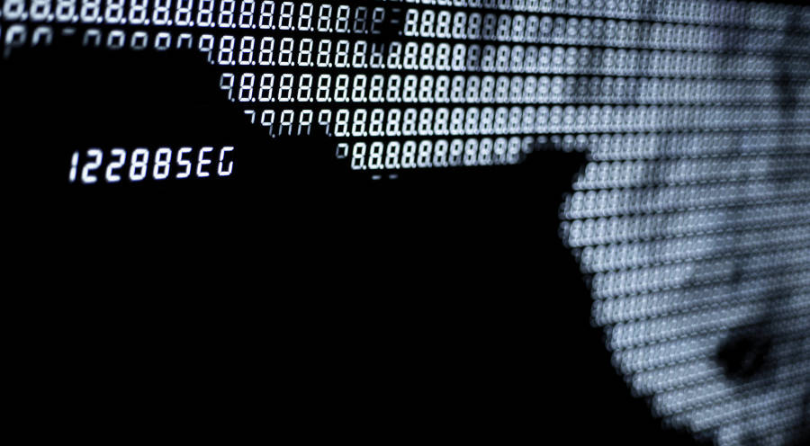
The LED displays are encased in an “smoked” acrylic box and the back plate is made from laser cut steel.
Outcome
More images can be found on the project page.